
Description
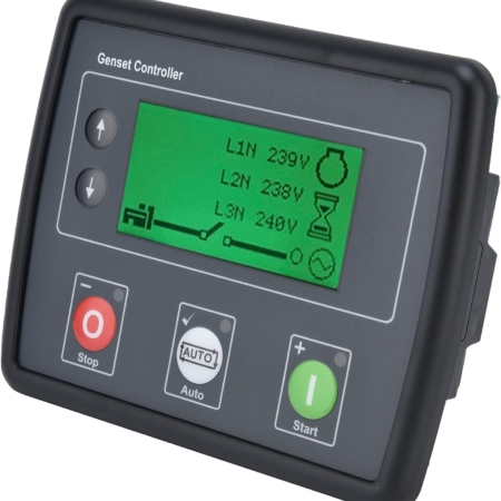
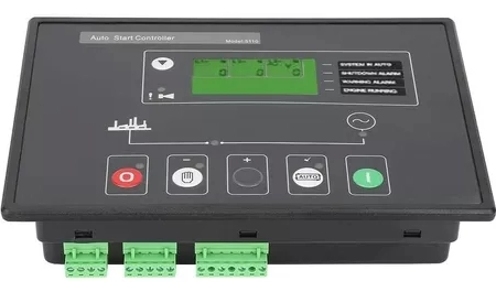
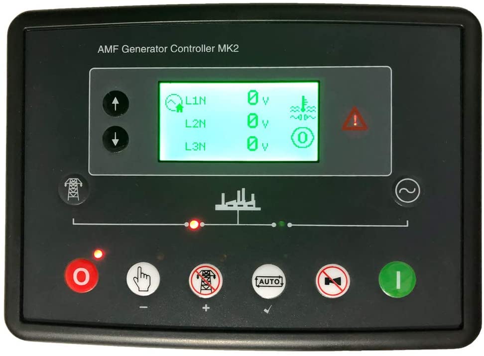
The DSE 6020 MKII is an automatic grid fault control module (utilities) developed to provide a wide range of operation and monitoring functions for individual gas and diesel generator sets.
KEY FEATURES: KEY BENEFITS –
Support for 0-10V and 4-20mA oil pressure transmitters: provides flexibility for use with multiple sensors and motor types.
-Large LCD display with backlit icons: displays information to the operator in a clear and concise format.
-Heated Display Option: Ensures that the display continues to function in extremely cold weather conditions.
-Three-phase generator detection: provides true generator detection.
– Three-phase generator and mains detection (utility): Provides true generator and mains detection (utility).
-Front fascia circuit breaker control buttons: Instant circuit breaker control when working with a control module.
-Load and generator power monitoring (kW, kV A, kV Ar, pf): provides clear and accurate power measurement information.
-Generator Overload Protection (kW): Provides clear, easy-to-read information pages.
-Load/generator current monitoring and protection: Provides the convenience of monitoring and protecting the generator or monitoring the load current.
-Configurable analog/digital inputs: provides multiple installation options.
-Configurable staged, voltage-free, and DC load outputs: Provides full control of the generator load.
-CAN, MPU and alternator speed sensor (selectable depending on engine type): Makes the module ideal for standard and electronic engine applications.
-Level 4 CAN Motor Support: Ensures that the control module can be used with the latest in modern electronic motor technology.
-Configurable Event Log (50): Provides access to historical alarms and operational
status-DSE Configuration Suite PC Software: Provides comprehensive, easy-to-use configuration and high-level, easy-to-use system control and monitoring.
-Fuel and starting outlets (configurable in CAN): Offers multiple installation options.
SPECIFICATION-DC
Supply- CONTINUOUS VOLTAGE RATING
— 8V to 35V continuous
– STARTER DROPS
— Capable of surviving at 0 V for 50 mS, provided the supply is at least 10 V before the drop and the supply is recovered to 5 V. This is achieved without the need for internal batteries. The LEDs and backlight will not be maintained during boot-up.
–MAXIMUM OPERATING CURRENT
— 100 mA at 12 V, 105 mA at 24 V
–MAXIMUM STANDBY CURRENT
— 60 mA at 12 V, 55 mA at 24 V
–MAXIMUM SLEEP CURRENT
— 40 mA at 12 V, 35 mA at 24 V
-GENERATOR AND GRID (UTILITY)
–VOLTAGE RANGE
— 15 V to 415 V AC (phase to N)
— 26 V to 719 V AC (phase to phase)
–FREQUENCY RANGE
— 3.5 Hz to 75 Hz
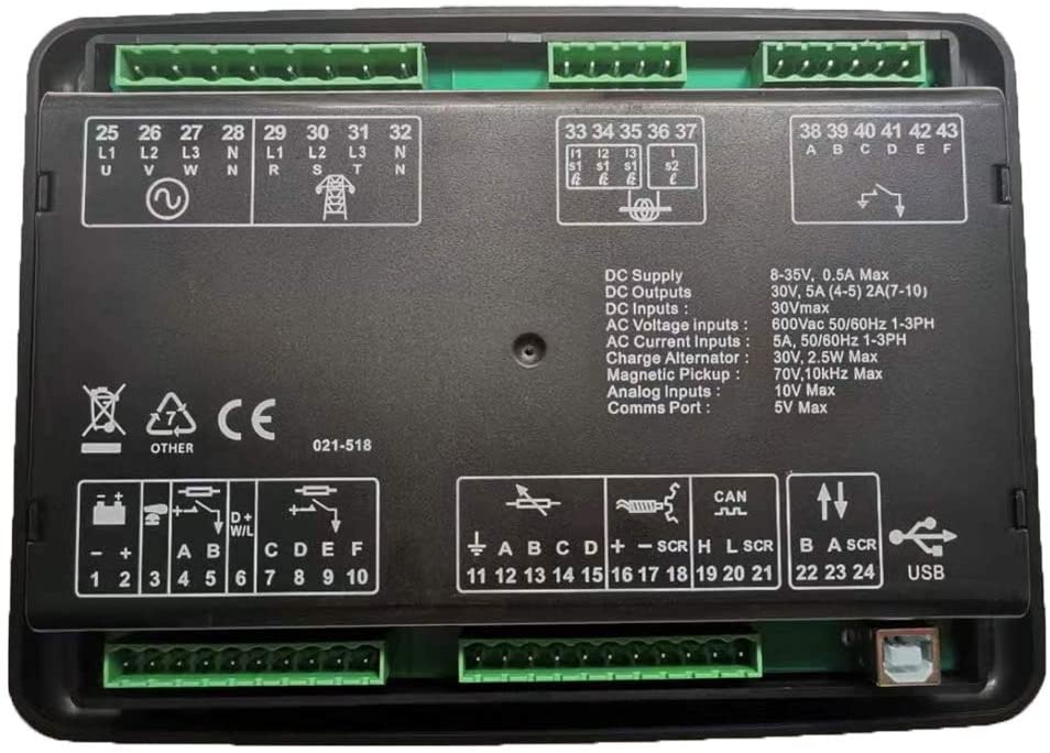
-INPUTS- DIGITAL INPUTS
A TO F
— Negative switching
-ANALOG INPUTS A to C
– Configurable as: Negative switching digital input 0 Ω to 480 Ω
-ANALOG INPUT D
– Configurable as:
Negative
switching digital input 0 V up to 10 V
4 mA up to 20 mA
0 Ω to 480 Ω
-Outputs
– OUTPUT A (FUEL)
— 10 Short-term, 5 A continuous, with supply voltage
– OUTPUT B (START)
— 10 Short-term, 5 A continuous, with supply voltage
– AUXILIARY OUTPUTS C, D, E and F
— 2 A DC with supply voltage